What should you be thinking about?
There are many questions you need to be asking to ensure you’re going to choose the right hydraulic filter for your needs.
What is the pipe size?
Flow rate and pipe size go hand in hand. The filter must be properly sized to keep the pressure drop compatible with the fluid passing through it. A pump putting out 50 gpm, for example, will create less pressure drop when going through a 3-in. npt (American National Standard Taper Pipe Thread) pipe than through a 1-in. npt pipe. The pipe size will help focus filter selection.
Typically flow velocities in hydraulic subsystems should be high enough to ensure the subsystems run smoothly and efficiently. In pump suction lines, flows should be travelling roughly 2 to 4 ft per second (fps); in pressure lines, 10 to 25 fps is the range for fluid velocities; and for return lines, the figure is 5 to 10 fps.
What is the working system pressure?
The answer to this question will let designers choose a filter that will withstand that anticipated pressure. If the filter can’t and it collapses, it will likely lose its integrity, break down, damage the entire hydraulic subsystem and lead to a possible breakdown. To make matters worse, when a filter collapses, fragments of epoxy or filter media are injected into the flow stream and can damage downstream equipment.
What is the fluid?
Is it standard hydraulic fluid? Is it a petroleum-based product compatible with the equipment? These answers will let designers and operators know if the fluid is compatible with all system components as well as filters. If it is not, be prepared for serious system damage or destruction.
For example, if phosphate ester is the process fluid, polyester, nylon and stainless steel filter media are fine, but polypropylene is unacceptable. Standard hydraulic oils are compatible with filter media such as cellulose, polyester, polypropylene, stainless steel and most other types of media. The point is to ensure that the process fluid, filter media and seal material are all compatible. If there are any compatibility issues in any area, there will be leaks and major contamination problems
What is the fluid’s viscosity?
Standard hydraulic fluid has a viscosity of 150 to 200 seconds for 60 ml of oil to flow through a standard orifice at a given temperature. Any fluid with a higher viscosity is thicker than standard hydraulic fluid. Fluids with higher viscosities create higher pressure drops as they flow through the system, especially during cold weather start-ups.
Designers and operators should be aware that allowable initial pressure drops vary widely from component to component and so they should know system requirements for pressure and ensure they will be met.
What type of pump is being used?
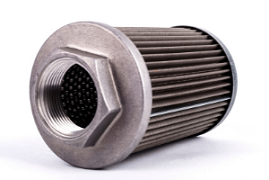
Is it a piston, gear, vane or other type of pump? This is important to know when installing a new or replacement suction strainer. Suction strainers keep contaminants out of the pump, the most important component in a hydraulic subsystem.
Different types of pumps sometimes require more protection. The chart below provides general guidelines for adequately protecting hydraulic pumps.
What mesh or micron should be used?
To completely size a filter, knowing the filtration level is critical to efficiency. Suction lines should be no finer than 200 mesh (74 micron). Having filtration that is too fine on the suction side can cause pump cavitation.
Typically, the pressure line has the finest filtration in the system because it is the most critical. So, the pressure line filter mesh could be in the sub-micron area, depending on the application.
The return line should be anywhere from 5 to 74 microns, again depending on the application. This is an area that should be looked at closely because applications, requirements and operational scenarios vary so much.
Fluid Viscosity
One factor that is often overlooked when sizing hydraulic filters is fluid viscosity. Viscosity plays an important role in filter sizing, so ignoring it can result in the use of improperly sized filters.
Using a filter that is too big or too small can lead to unnecessarily high operating costs, a larger footprint, high pressure drop, higher replacement costs, and premature tripping of clogging indicators.
Clogging Indicators
If a filter becomes clogged, this can be dangerous to the health of a hydraulic system. A clogged filter will starve the pump of hydraulic oil and the RPM will increase.
This is often referred to as a catastrophic failure, as the pump will eventually burn out. A high pitch sound can indicate that a clog is forming, and the sound is caused by the increase in pump RPMs.
A hydraulic filter with a relief valve will activate if pressure exceeds safe limits, eliminating the risk of cavitation and pump failure.
We hope the above guidance will help with sizing your hydraulic filters, for more information or advice, our technical team are here to help, simply contact our team.